Radio Link
I can be contacted at E-mail address:-
![]()
Radio LinkI can be contacted at E-mail address:-
|
|
|
The Radio Link pane: To open the Radio Link pane, press 'F2' or click on the 'Radio Link' Toolbar icon
alternatively open 'Tools/Radio Link', this will open an active Radio Link Pane in which the Base to Mobile link will be displayed.
Click here for a summary of keyboard shortcuts. Click here to export a link into Google Earth. Click here to see where the signal level colour thresholds can be changed. (But also see the changes in the way Distance is measured, which is dependent on the Elevation Data Extraction method here). Click here for an Antenna Pattern Viewer illustration. Click here for a Land Cover illustration.
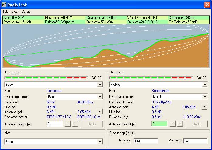
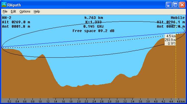
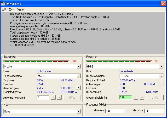
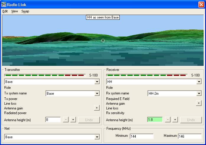
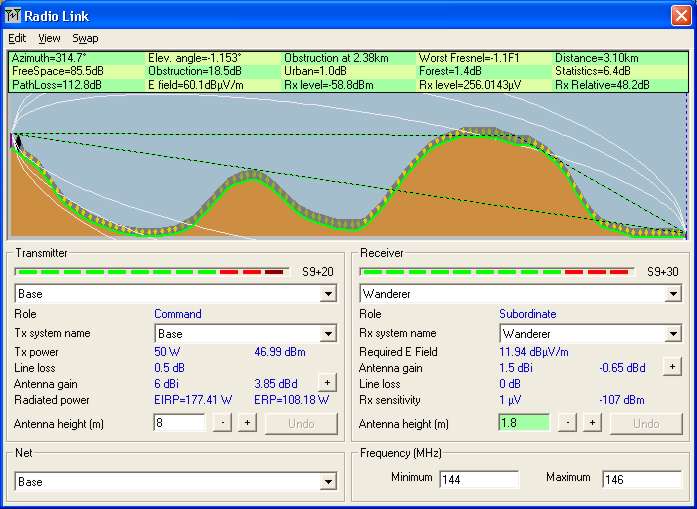
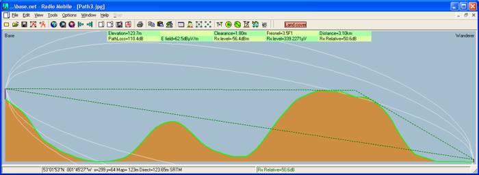
This is the default initial 'Profile' view:
This pane gives all the link parameters between selected Units - whilst 'Swap' changes the transmission direction displayed.
A ground profile of the selected path is shown, with a mouse click in the coloured window moving the reference cursor to that point where the location parameters will be displayed. A click in the Green Data area at the top of the pane moves the cursor to the 'Worst Fresnel' obstruction location, whilst 'Shift+Left click' moves the cursor to the start, and 'Shift+Right click' moves the cursor to the end of the link. This cursor can also be moved by using the left and right 'Direction arrow' buttons. A 'Shift+ L/R arrow' causes the cursor to move to that end of the path, whilst an 'Up arrow' moves the cursor to the 'Worst Fresnel' obstruction position.
The Receiver Antenna Height box is highlighted in green to show that it is active. To transfer activation to the Transmitter height box use ‘Ctrl+[‘ keys, and return to the Receiver height box by using ‘Ctrl+]’ keys.
The selected antenna height can be adjusted in 1m increments using the ‘Page up’ and ‘Page Down’ keys which retains the use of the Profile arrow keys. ‘Shift-Page Up/Down’ changes the selected antenna height in 0.1m increments, whilst ‘Ctrl-Page Up/Down’ produces 10m increments. All changes are reflected in the Profile display. As soon as the starting antenna height is changed, the 'Undo' button becomes active until the antenna height is readjusted back to the start value, but note the use of this button in the next paragraph.
A mouse click on the + or – button by an antenna height box will select and change that antenna height in 0.5m increments, and an ‘Enter’ will repeat the action. A click on the ‘Undo’ button returns the antenna height to the start setting. Clicking in the Antenna Height box enables the direct entry of heights, with all the changes being reflected on the Profile display. These actions move the program focus to the height box which removes the Profile cursor functions.
To make the Profile cursor arrow keys active once more use ‘Ctrl-P’ to move focus back on to the Profile area before using them.
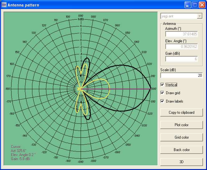
A click on the + button on the Antenna Gain line, opens an antenna pattern viewer which shows the selected system antenna pattern and azimuth of the path selected.
To see the screenshots, click Antenna Pattern Viewer
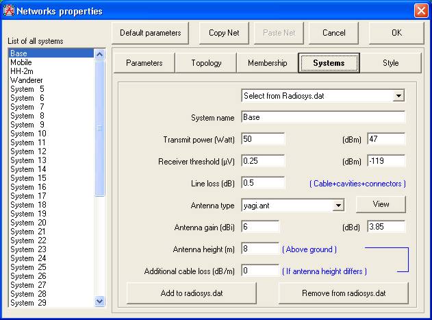
The Transmit and Receive Systems may also be changed using the 'drop down list' by the System Name.
The S meter indicators give a visual representation of the received signal strength for each direction of transmission, (values dependent on the settings in 'Options/S-Unit). The indicator under 'Transmitter' showing the reverse path received signal strength.
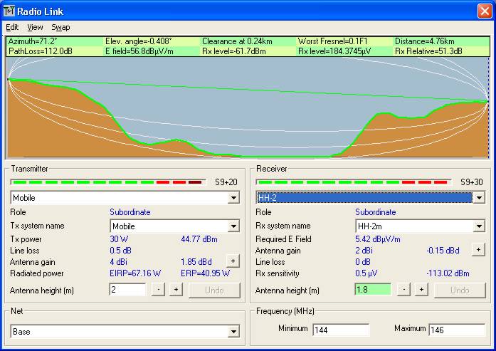
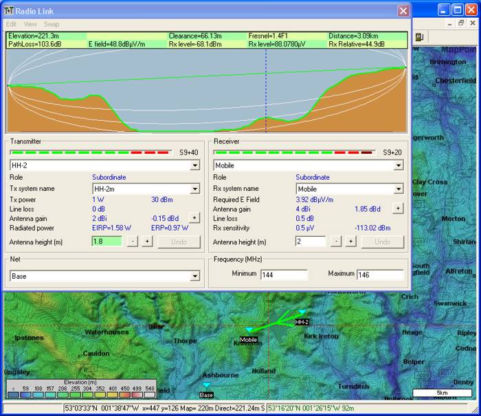
Mobile to HH-2 path can then be selected.
It should be also noted that the main window will show the cursor position on its path display using the red cross wires.
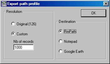
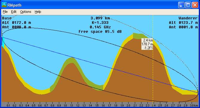
By opening 'Edit/Export to' or using 'Ctl+F9' then selecting RMPath,
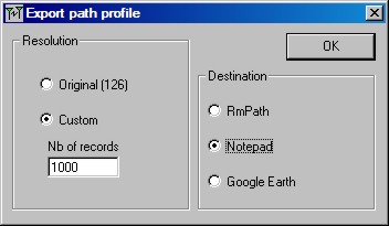
where the number of records to be generated can be made, and on pressing OK, you will be asked to save the path profile, and then the following pane will open. In RMPath you have the option of showing more Fresnel Zone data for microwave studies:
As an alternative, on the 'Export Path Profile' pane, Notepad may be selected as the destination. The Profile.txt file is then saved without opening RMPath. The contents of this .txt file can then be imported into Excel for further analysis if required.
Exporting the Link to Google Earth:
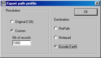
Finally, selecting Google Earth as the export path,
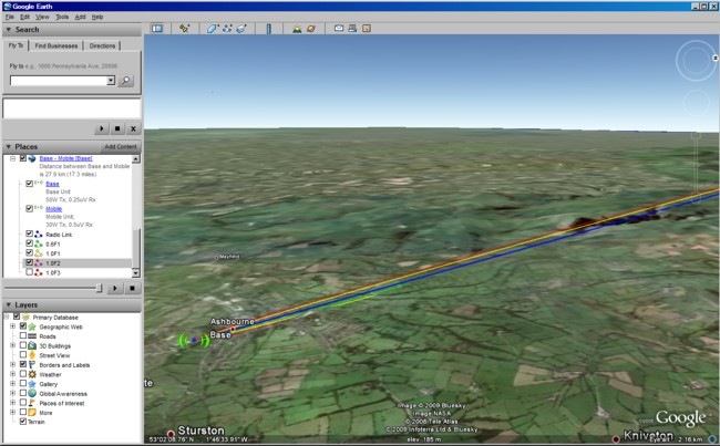
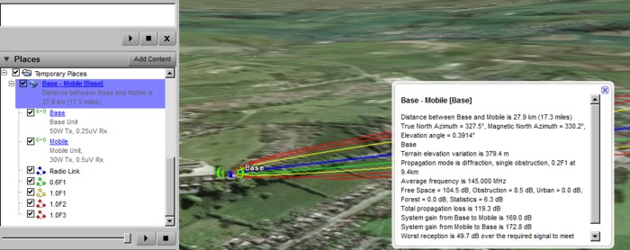
again generates a prompt to save the Profile.txt file on clicking OK, but after the file is saved, Google Earth will open (if installed on your computer), and show the full Radio Link with Fresnel zone indications.
A Green line shows 0.6F1 on the clearance side, A Yellow line shows 1.0F1, Other Fresnel zones will be shown in Red. The 0.6F1 and 1.0F1 lines are only shown where visible.
Opening the 'Temporary place' file in Google Earth control area, allows the selection of the Fresnel zones to be displayed, whilst a 'Left Click' on the file names opens a descriptive pane showing the details of the Link or Unit.
Note: to display the transmitter icon above, if you have an old installation, you will need to place the file 'antenna.png' in the root of your Radio Mobile folder - available here. (Right click and 'save target as').
This file is now available in RMCore.zip on Roger's Download page.
In the Radio Link pane, opening 'View/Details' produces the Link data which can be copied or exported to Notepad as shown here:
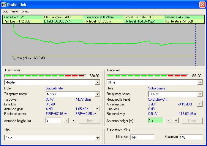
Whilst 'View/Range' gives this screen, which can have the cursor moved to any point as above:
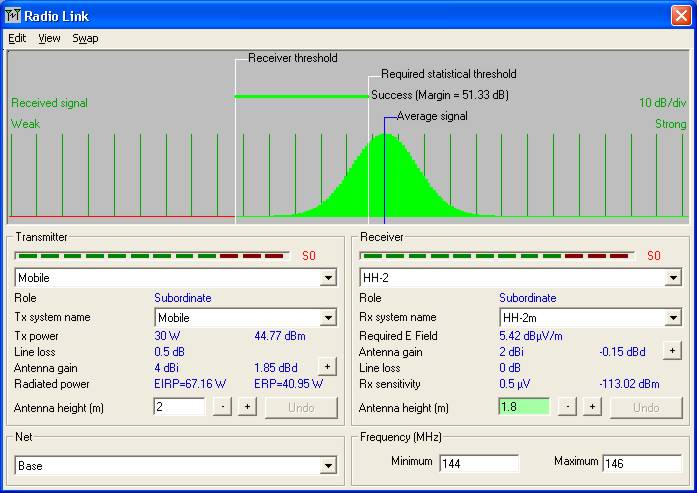
and 'View/Distribution' shows the statistics of the signal path:
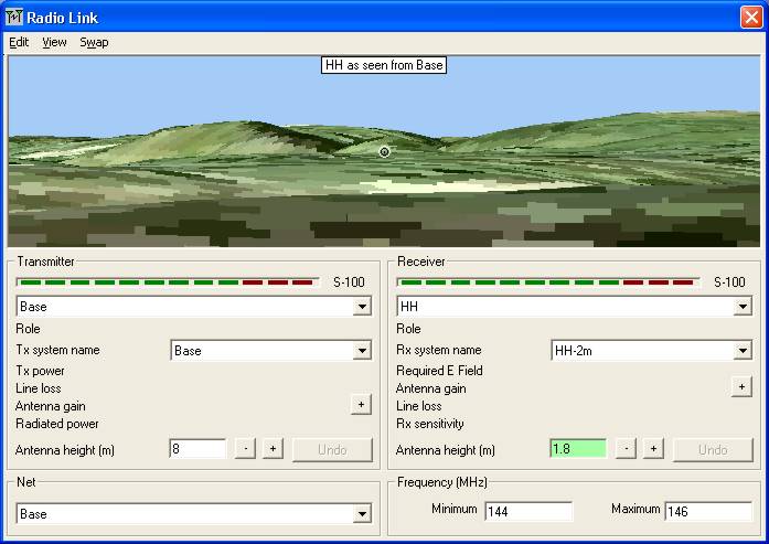
If 'View/Observe-20˚ ' is opened in the Radio Link pane, (or use Ctrl-F3), for the Base to HH link, the link display is changed to a view of the receiving antenna from the transmit antenna - if visible the Rx antenna is shown by a circle. The view colours corresponding to the elevation data.
If an aerial photograph has been merged over a map and saved as a new picture under its own name, (to reference it to the elevation matrix), and the photograph is the active window, the 'View/Observe-20˚ ' function (or Ctrl-F3) in the Radio Link pane will produce a view of the photo image superimposed on the elevation matrix.
A large window can be produced if required and a Stereoscopic picture obtained to give a 3D effect when viewed through Red/Blue glasses.
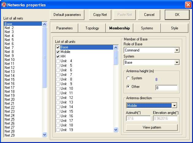
Where a gain antenna is in use, the pattern viewer will show the actual bearing and gain achieved for the antenna This can be demonstrated by changing the Base Unit 'Network System' to the Yagi antenna:
Set to point at the Mobile Unit:
Where the Radio Path Azimuth and Elevation can be seen greyed out.
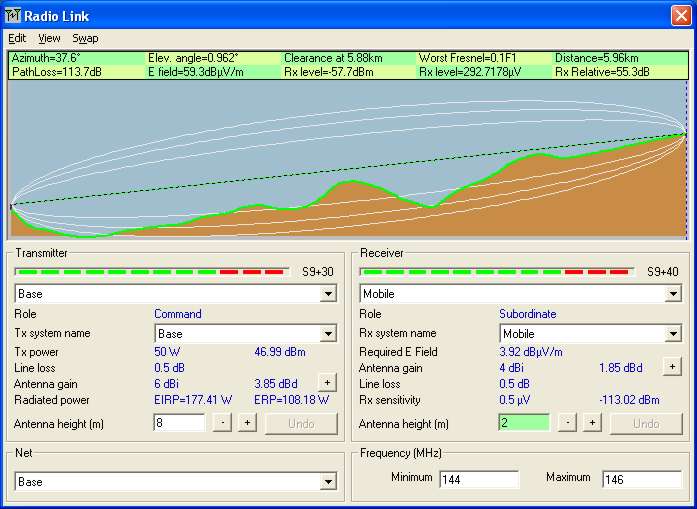
Now, opening the Radio Link pane to show the Base to Mobile link:
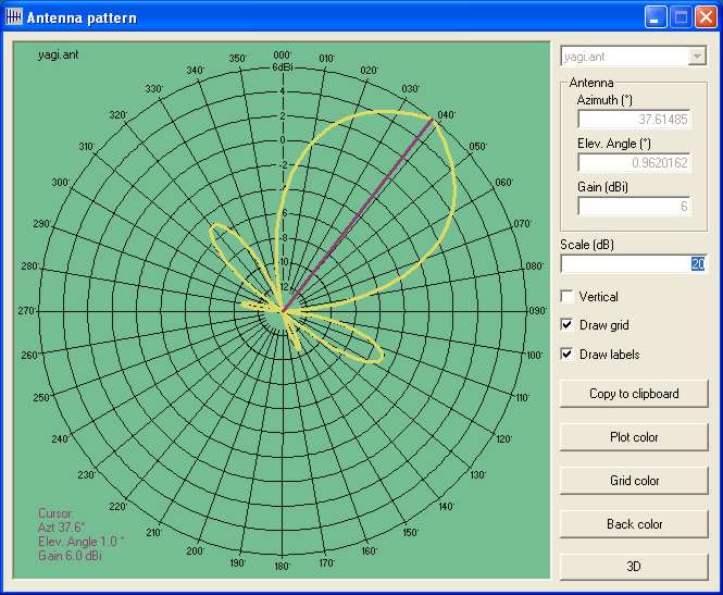
and clicking on the + button by the Base antenna shows:
Where the purple line shows Azimuth of the Mobile Unit to which the antenna is pointing.
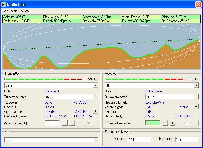
Changing the Radio Link pane to show the Base to Hand Held path:
and again clicking on the + button by the Base antenna shows:
Where the Azimuth of this path is again shown on the antenna pattern which points to the Mobile Unit.
Next selecting the Vertical view:
Now shows the actual vertical gain of the antenna 'off beam' towards the Mobile Unit.
For a full
description click
When using the Radio Link pane, it is also possible to incorporate the losses caused by the Land foliage coverage impinging into the Radio Path.
To see how, visit:
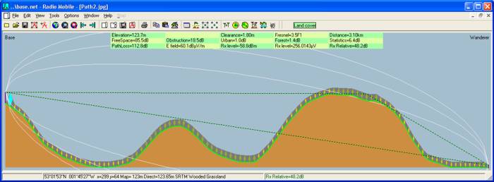
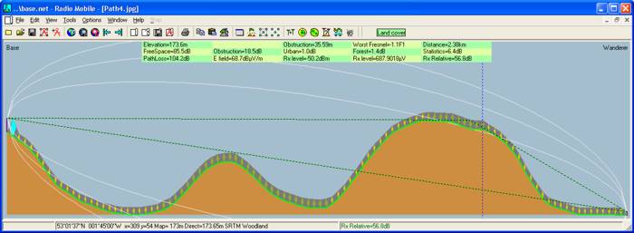
The Radio Link pane below shows how Land cover data is represented, and how it can intercept the radio path:
With an additional set of loss data for the Landcover incursion
and the coverage data is also exported into RMpath
To find out how to use this feature go to:
To produce the above screen records, with the pane active, using 'Alt+Print Screen' will place a copy of the pane on the clipboard for insertion into a photo program. As an alternative, where only the path details are required rather than the full 'Radio Link' pane, using 'View/Large window' produces a large window of the path on the main program screen. This can then be saved to the clipboard using 'Edit/Copy'.
Placing the cursor at an intermediate point on the Radio path, and saving the Large window as above, shows the link details and the type of Land cover at that point in the bottom data region of the window.
However, if Land Cover isn't invoked, the details of the additional losses aren't displayed.
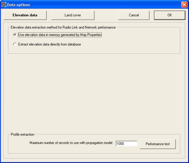
If you check 'Options/Elevation Data' and see it is as shown.
Where 'Use Elevation data in Memory generated by Map Properties' is selected, the Radio Link distances are calculated using Cartesian geometry - ground to ground - so the errors increase with the path length.
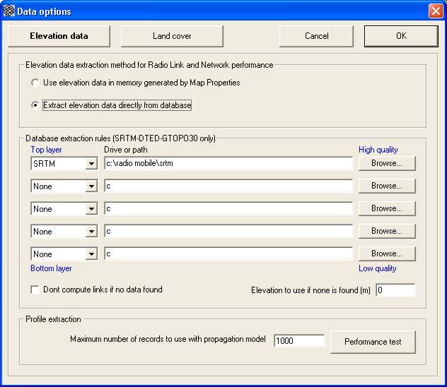
If you have a fast machine, you can use 'Extract elevation data directly from database', but do a 'Performance test' first before setting the Maximum No. of records to use.
(Note that the height data requires to be uncompressed to use this feature).
In this case with 'Extract Elevation Data directly from the Database' selected, the calculations use spherical (Great Circle) geometry. With this setting the reported distance is accurate between the antenna bases, regardless of distance.
This mode should be used in Microwave studies.
Summary of keyboard Shortcuts in Radio Link Pane
Action Effect
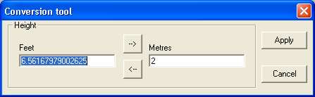
Yet another unexpected tool which is available is a Metric Converter. This is activated by a 'Shift+Left Click' on any metric window - like the Mobile Antenna Height box above. It is also available from 'Tools/Metric Conversion', or by using the 'Control+M' keys on the keyboard.
This page is available in .pdf format here
Please keep checking back for updates/additions.
© Copyright G3TVU 26th October 2017
| |||||||||||||||||||||||||||||||||||||||||||||||||||||||||||||||||||||||||||||||||||||||||

