Base Network Settings
I can be contacted at E-mail address:-
![]()
Base Network SettingsI can be contacted at E-mail address:-
|
|
|
Note: If you wish to change the installation directory to your 'H' drive, see the notes shown as '*Blue', but if the installation directory is changed, the installed 'Radio Mobile' program will initially open with a blank frame which allows the settings to be adjusted.
Click here for details of my 'Quick Start' Updated details on reconfiguring to your own location can be downloaded HERE. Para la versión española de la reconfiguración - Haga clic AQUI.
Click the titles below to go to the sections:
Internet Downloaded Data Paths Base map Elevation Legend location
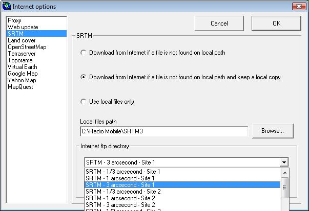
To see the Internet Elevation Data path after installation, which defines where downloaded elevation data is to be placed, Click on 'Options/Internet' to produce the pane below, also check that the 'Internet ftp directory' is as shown and Cancel. But see the Changing Location page if you want to move the map centre!
(* Change Local file path H:\Radio Mobile\SRTM3)
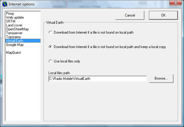
Internet Downloaded Data Paths: Folders for all the other enabled internet download data sources have been generated, and set to their default locations in the Radio Mobile folder using the above Internet download pane.
(* Change all local file paths to H:\Radio Mobile\..... ) (Applies to Land cover, OpenStreetMap, Terraserver, Toporama etc.)
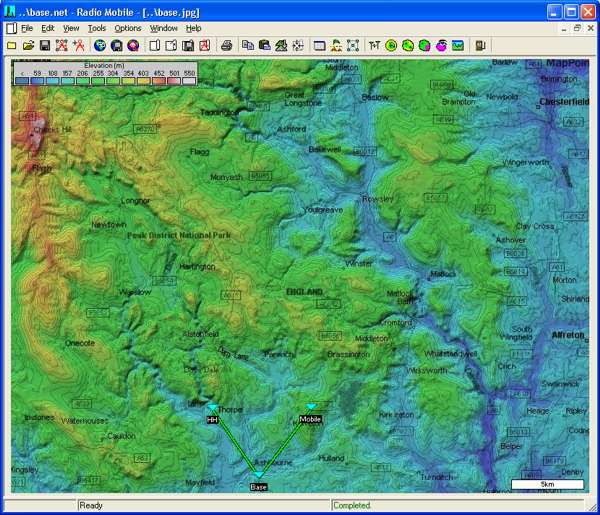
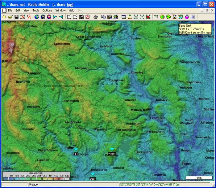
Enlarging base.jpg to full screen, gives the following screen which shows a Network consisting of a Base unit plus a Mobile and Hand Held Unit. If the Units aren't visible, click on 'View/Show Networks/all',
or the Toolbar Icon
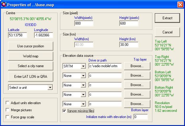
Click on 'File/Map Properties' to open this window, and check that SRTM is selected from the top layer Elevation Data Source drop down list, Making sure 'Ignore Missing Files' is checked! - Click Extract if you change anything, otherwise click Cancel.
(* Change SRTM path to H:\Radio Mobile\SRTM)
(and see the Notes ref the QRA locations if you wish to use MGRS)
(If you Click Extract it will generate a new map without any embellishments from the external data source or elevation contours, this can then be closed to avoid over-writing my modified initial map which is already available under the same name. This is the window where the map size/location can be changed, but the new map will only show elevation data as has just been demonstrated. (To replace the elevation map use 'File/open picture' and click on Base.jpg)).
(To produce a new road map if you have changed the map location, open the BW window and do a Merge/copy from a selected data source and keep in the picture, greyscale can be forced by Edit/Greyscale - not forgetting to save the picture using 'save as' under your own new name!)
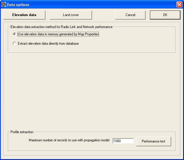
It is also useful to check 'Options/Elevation Data' to make sure it is as shown.
Note: Where 'Elevation data in Memory' is used, the Radio Link distances are calculated using Cartesian geometry - ground to ground - so the errors increase with the path length, and antenna height has no effect.
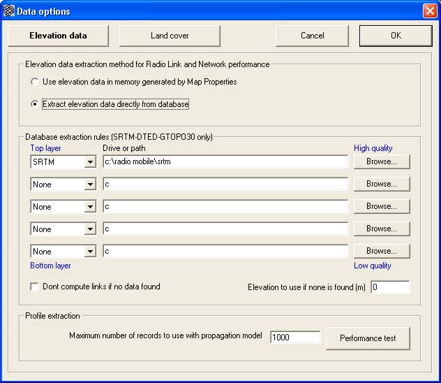
If you have a fast machine, you can use 'Extract elevation data directly from database', but do a 'Performance test' first before setting the Max No. of records to use. (The height data requires to be uncompressed to use this feature).
(* Change SRTM path to H:\Radio Mobile\SRTM)
Note: With 'Extract Elevation Data directly from the Database', the calculations use spherical (Great Circle) geometry. In this case the reported distance is between the antenna bases, so it will not vary with antenna height. This mode should be used in Microwave studies.
* Finally, to obtain a working map after changing the program file folder location, select 'File/Open Networks', open the 'Base Network' folder, and select Base.net.
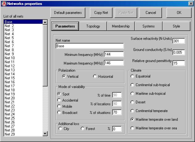
The parameters of 'Base' Network can be examined by opening 'File/Network Properties'
or by clicking on the Toolbar Icon
to give the Parameters of the VHF network set for my climate:-
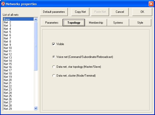
A click on the Topology button will open the pane below showing that a visible voice network format has been selected for use.
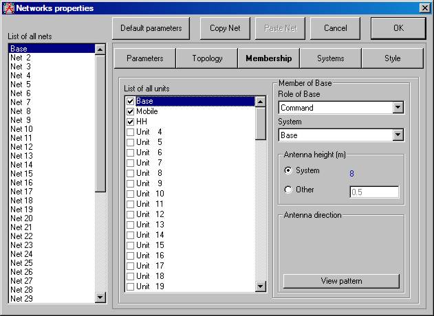
Next, clicking on the 'Membership' button, shows the three members of Base Net with their Roles and Systems:
Base as Command:
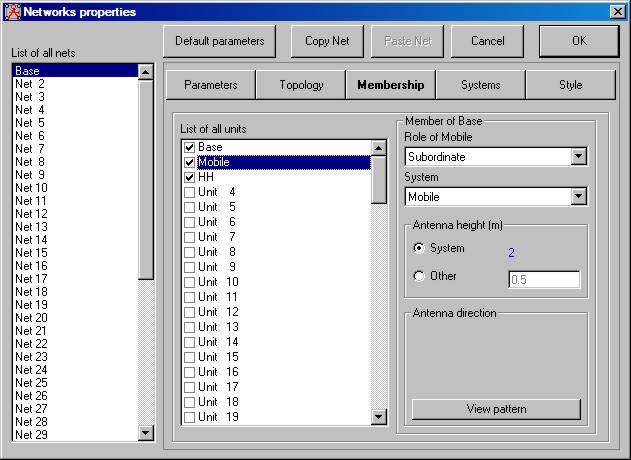
Mobile as a Subordinate:
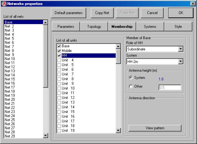
and a Hand Held Unit also as a Subordinate:
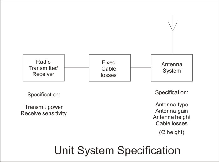
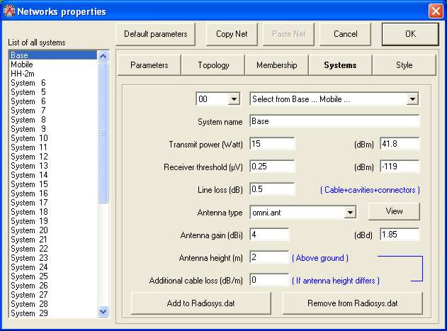
A Radio System defines all the properties of a particular Unit as shown here:
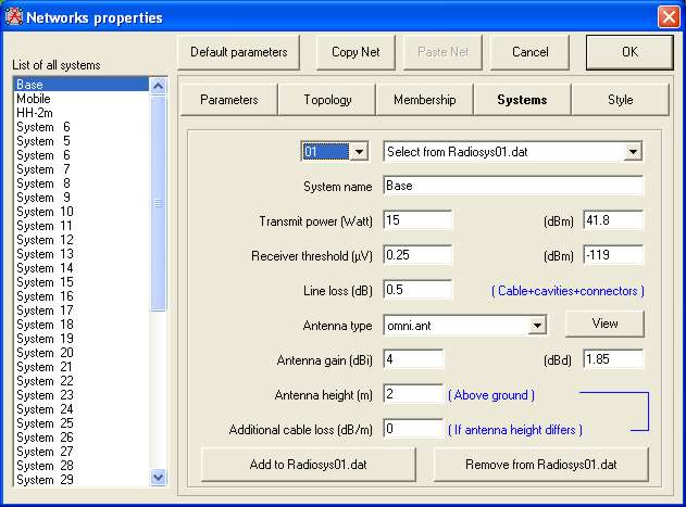
Clicking on 'Systems' in the Network Properties pane then shows three Radio Systems have been defined for the Base Network, the first System relates to a Base Unit:
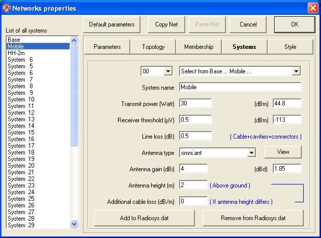
The second System relates to a Mobile unit:
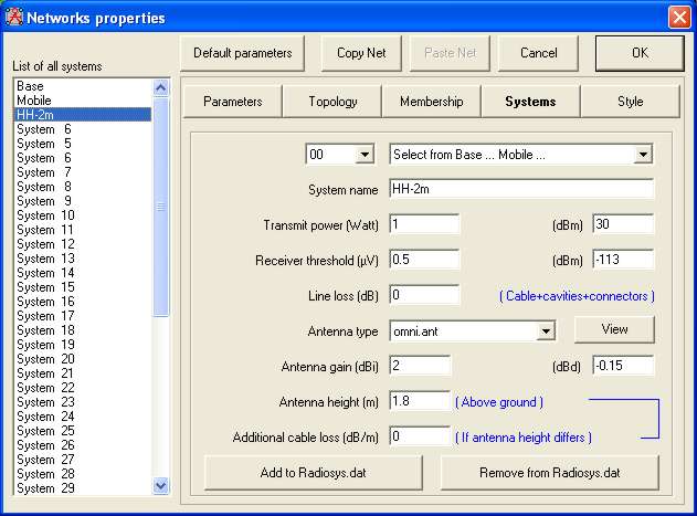
and the third System relates to a Hand Held 2 metre Unit:
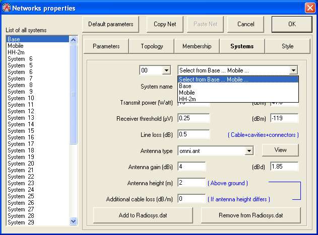
The required system group settings to be applied are shown with a serial number - number '00' referring to Radiosys.dat - the default 'System Group' setting. The 'Select from...' panel shows the first two System definitions contained in the '00' Group as an aid to identifying its contents.
The Systems shown in the 'List of all systems' can be selectively saved into another suitable Group using the buttons at the bottom of the pane - the names on which reflect the serial number of the 'System Group' selected in the Number drop down list. If the selected Group has no entries the 'Select from...' display will be as shown.
The System Group feature allows the set of Radio Operating Systems appropriate to a given Network to be saved with that network - this can be used to separate various frequency Systems - or perhaps Networks using different manufacturers equipment types.
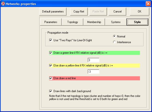
A click on the Style button shows the definitions selected for the Network signal path displays, where a +/-3dB signal level relative to receiver sensitivity is selected as a Yellow line. Signals >3dB being shown in Green, and <-3dB shown as Red. The check boxes adjacent to the coloured lines define whether a Network display shows these colours on the plot - i.e. only Green signal level links could be selected showing signals links >+3dB above the receiver threshold. Changing the level (dB) settings, alters the threshold colour contour overlay line plots for the Radio Link and Route panes, and also the drawn Route.
- Note that the check box selection doesn't apply to these plots, only the Network plot!
With a Network, Radio Link and Route plot, the Yellow overlay colour can be removed by selecting the same level in the two 'dB' boxes, to give a display with Green and Red plots only.
Network Style plots are also available on the Polar and Combined Cartesian coverage plot panes where the signal limits set define where the coloured regions are plotted. By setting the two dB limits equal the Yellow region is disabled and a Compliance plot can be performed showing areas where signals above the preset limit are available as a Green area - with all other areas as Red.
But see Network, Radio Link and Route Styles for screenshots of the effects!
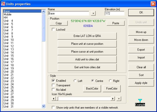
Closing this window and opening 'File/Unit Properties',
or by clicking on the Toolbar Icon
allows Units to be enabled, moved in the list, relocated, renamed and Icons selected with their name position defined:
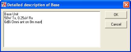
As an additional feature, a click on the + button by the Unit Name, opens the following pane where a description of the Unit can be saved.
The significance of this description pane is that, by performing a 'left click' on the Unit, the description will be displayed on the main screen as shown below. A left click on the description message closes it.
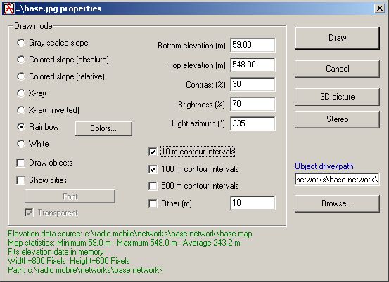
The Base map Elevation legend is visible and placed in the Top Left corner of a plot by default. If you wish to change its location - or not have it displayed - open the 'File/Picture properties' pane for your plot background picture to show:
This pane is where the details of the picture displayed can be seen. The bottom Green text giving all the data relative to the picture, including the data source location.
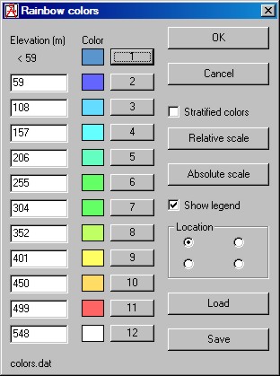
When Rainbow colours are selected as the Draw Mode, a left click on the Colours button produces another pane where the displayed colours and elevation ranges may be changed. At the lower right of this pane is the area controlling the legend position, with a check box to disable it.
A click on the 'Load' button opens a browse pane where alternate colour pallets can be loaded. There are files named 'Color1.dat' to 'Color5.dat' available. Alternatively, by clicking on a numbered button on the pane above, you can select the displayed colour of your own preference for each band. You can then save the resulting custom pallet under your own name by using the 'Save' button.
The Icon symbol required for a Unit can be selected using the arrow buttons or slider at the bottom of the Style area of the 'Unit Properties' pane. A click on the '+' button will open the pane below. This shows the Icon symbols available from the program and those present in the Icon folder. This table enables a quick selection of a suitable Icon from those available by a double click. Additional Icons can be added to this folder as required, but should be 16x16 or 32x32 pixels in size. There are 90 icons pre-programmed into the program, up to and including the 'Radio Mobile' icon, plus an initial blank. The remaining icons can be replaced or deleted as required from the Icon folder, up to a maximum of 1023 total. It should be noted that alpha-numeric labels without an icon can be generated by selecting the initial 'Blank' icon position. These labels can have the background and text colours selected from the Unit Properties pane as required.
Note that additional new icons have been added as shown at the bottom of the pane - these are designed in four sets, and allow multiple units to be placed at a single location in 2,3 or 4 unit sets. The required format set can be selected, and individual units given a colour to identify a particular link. If the location needs to be identified, a common label can be used for the units - or a single one, with the other icons selected without labels. To see how these 'multiple unit at one location' icons can be used, click Here.
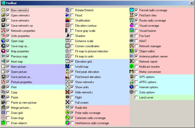
A right click on the toolbar opens the following pane where the required tools for display on the Toolbar can be selected.
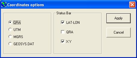
QRA, MGRS or other location reference selection: In the above panes an 'Enter LAT LON or QRA' button can be seen, with a QRA location shown above - the 'Quick Start' installed files show this. If the Military Grid or other locator is required, select 'Options/Coordinates' to produce the pane below, where the desired selection can be made. The Status Bar coordinate data to be displayed can also be selected from this pane.
Problems? If so, please go through this check list first:-
1) Is the correct Elevation Data Path set up in Internet Options? 2) Is the correct Data path set up in Map Properties? If your machine freezes, make sure 'Ignore Missing Files' is checked. 3) Can't get a Map when changing Location? Make sure you have selected your region for the SRTM data in 'Internet Options'. 4) No Units? Make sure that you have units enabled in both Network and Unit Properties. Use 'Move Unit to Cursor position' in 'Unit Properties' to place units on your map locations. 5) Can't get rid of my network? When you have generated your own network, cycle through all the windows, closing those which don't apply to it. Then save the map, all pictures and network under your new names. 6) You can see the QRA locator reference rather than MGRS - see Notes.
7) If you are unable to 'merge' pictures from external sources read this 'Important Note'.
This page is available in .pdf format here
Please keep checking back for updates/additions.
© Copyright G3TVU 26th October 2017
|