Find Best Sites - 2
I can be contacted at E-mail address:-
![]()
Find Best Sites - 2I can be contacted at E-mail address:-
|
|
|
There are two methods of Finding best sites, the first was in a Network and this second by using Waypoints.
A click on an image on the page will take you to a higher resolution picture, 'Up' or 'Back' to return.
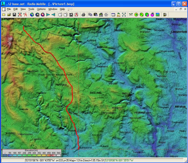
This Second method of Finding Best Sites uses Waypoints generated by the Object Editor. The map below of my modified Base Network, has had a Road Route drawn in red upon it. This Route has to be traversed by a Hand Held Unit which is required to communicate with a suitably placed Base Unit. (This route can be found as 'L1X-Ash-Bux.plt' in the 'Networks/Base' folder of the Radio Mobile folder). For this example, the 'Base' unit position is required to be towards its Home location in the North Eastern corner of the map as with the previous 'Within Network' description.
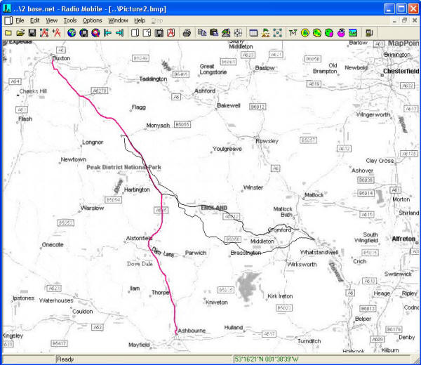
Selecting the Black/White window display, (this has had the route overdrawn for reference only), a 'Find Best Sites' plot can be performed using the Route Waypoints.
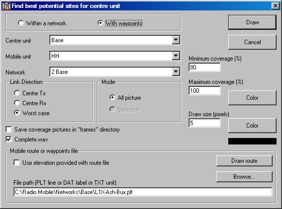
Opening 'Tools/Radio Coverage/Find Best Sites', pressing 'F5', or by clicking on the toolbar icon
will produce the pane below where 'With Waypoints' can to be selected to access this feature. Here the route, mobile plus centre Units and the required % coverage range are selected. The Draw Size is also selected, but bear in mind that a Cartesian Plot is performed for each Waypoint position for the pixel square area specified, so this can take a very long time. It is quite often better to perform a coarse plot to find areas of interest first. Selecting a Maximum coverage of less than 100% will produce a plot where the Maximum coverage shown will be equal or greater than that value.
Note: if you have previously accessed a different Network folder for a Waypoint file, the previous file location will be shown, and the Browse button will open that folder - however, deleting the File Path entry followed by use of the Browse button will cause the selected Network folder to be opened.
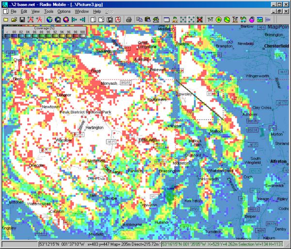
The following plot was produced for the Ashbourne-Buxton road route above.
Bearing in mind that one criteria was that the Base unit should be placed near to its Home location in the North Eastern area of the map, the area below was selected with a 'Left click and Drag' to generate the marquee box shown.
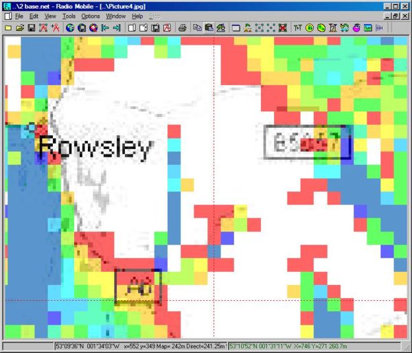
A right click on the marquee area produces a question as to if you wish to produce a zoomed picture, clicking Yes then generates the pane below which can be seen to be low resolution.
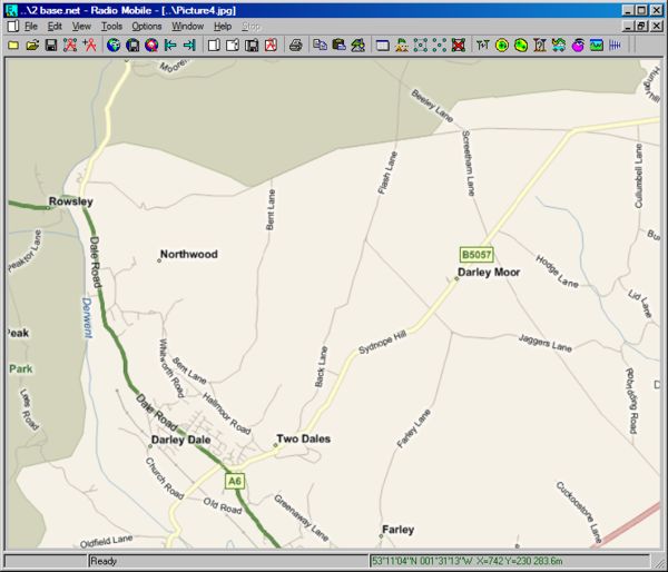
This picture can be merged - set to copy - with Virtual Earth Roads, and 'kept in the picture' to produce this picture of the area in high resolution.
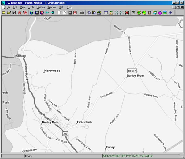
The picture is then 'Forced to Greyscale' by 'Edit/Force picture to greyscale' to produce this greyscale version of the picture, which again is 'Kept in picture' to replace the coloured version.
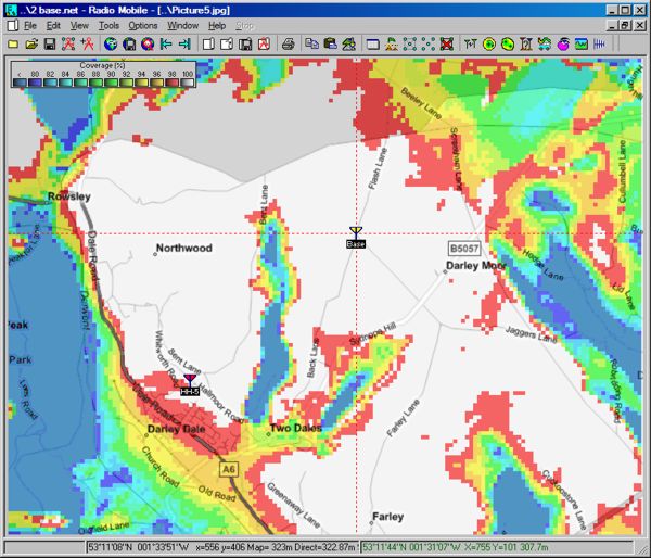
By once again performing a 'Find Best Sites' on the whole of this zoomed picture area, using waypoints, this final plot is achieved.
By clicking on the position required for the Base Unit on the cross roads - opening Unit Properties and then 'Place Unit at Cursor position' the following picture can be seen:
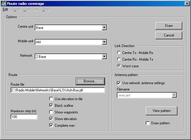
Finally, reopening the main Black/White window, and selecting 'Tools/Radio Coverage/Route', pressing 'F6', or clicking on the toolbar icon
will produce this Route Radio Coverage pane where the Route file is selected, and the Centre Unit, Mobile Unit and Network are defined. The 'Worst case' plot is selected to show where two-way communications are possible.
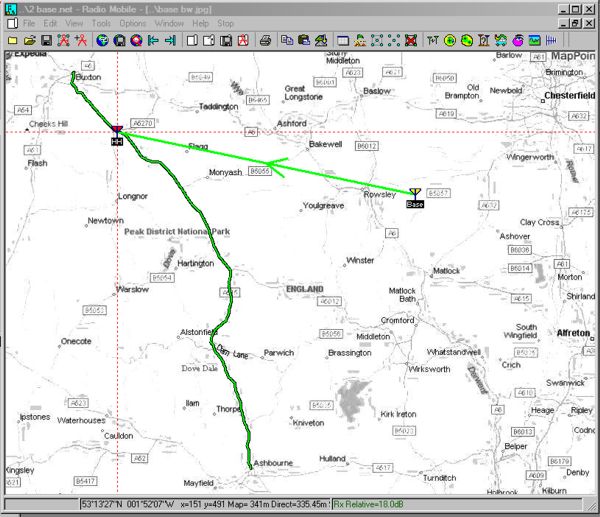
Pressing Draw then produces the route on the B/W map.
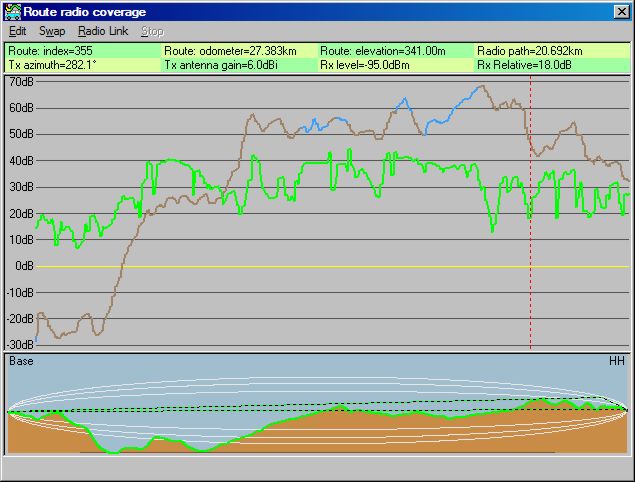
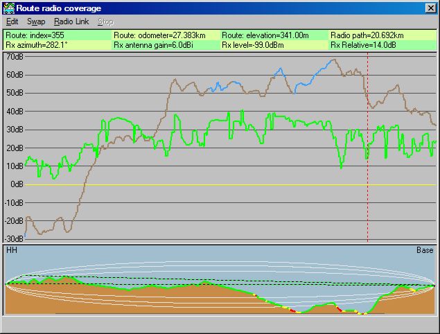
and the Route Coverage Display which can be navigated using the arrow buttons. The path profile below being updated at each step increment. This is the 'Worst case' plot which shows the lowest signal level available in two-way communication.
It will be noticed that the Elevation plot changes colour from Brown to Blue in certain areas - this denotes a Line of sight path between the Units.
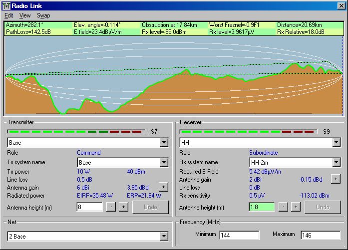
Clicking on 'Radio Link' allows the path from the present cursor position to the Centre Unit to be examined, or to any other Unit present in the Network. All the normal functions of the Radio Link pane are present, with the cursor reflecting points selected on the path. Closing the window re-establishes the Route Link.
Operating the 'Swap' function reverses the transmission direction, and indicates the true signal levels for that direction of transmission - from HH to Base.
Operating the 'Swap' function once more, reverses the transmission direction, and indicates the true signal levels for the reverse direction of transmission - from Base to HH.
This page is available in .pdf format here
Please keep checking back for updates/additions.
© Copyright G3TVU 26th October 2017
|