Route Radio Coverage
I can be contacted at E-mail address:-
![]()
Route Radio CoverageI can be contacted at E-mail address:-
|
|
|
This feature, allows a 'Route' to be drawn on a map, and the radio performance of a specified Transmitter/Receiver pair to be evaluated as one traverses the plotted route path.
For
information, I have included the next screenshots to show how a Route can be
generated, but to just try out the feature from a
'saved file' in my
Base Network, go to
Stage 2 here, for a more detailed
explanation of the use of the Object Editor and generation of Split Routes go to
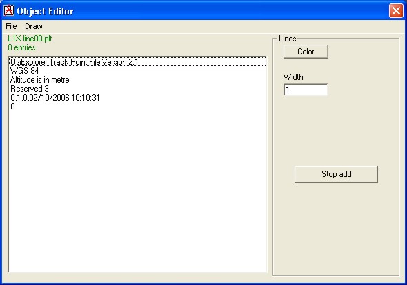
The required Route is defined by Waypoints, generated by the 'Object Editor', found under 'Tools/Object Editor'. Opening the Object Editor and entering 'File/New/Lines' will produce the pane below, where the Line width and colour can be specified. Every click on the map will enter a waypoint at that position, and when the required route has been completed, 'Stop Add' will finalise the route. The Route can then be saved using 'File/Save' function. (Note that the Object Editor now shows Altitude in metres, and has additional Control button functions).
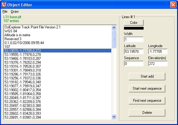
The 107 point route, as shown below, was saved using 'File/Save' for my Base.net, with the name 'L1X-base.plt'. This will be found in the root of my Base Network Radio Mobile folder using 'File/Load', and browsing to the folder.
In this pane condition - i.e. when 'Start Add' hasn't been enabled - a click on any entry will place the Cursor cross wires at the location of the highlighted Waypoint on the main map. The displayed Waypoint can be changed using the up/down arrows, with the Cursor reflecting the changed location. This pane can be moved around the screen by click-drag on its Blue title bar if it obscures the cursor on the main display. Activation of the 'Draw' command will cause the Route to be drawn on the active picture with the Width and Colour specified above.
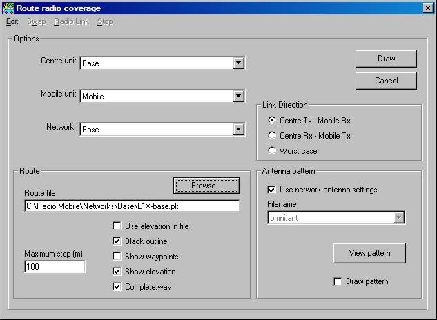
Open 'Tools/Radio coverage/Route' in my Base Network, which is the following pane, and browse to the file 'L1X-base.plt' shown:
Note: if you have previously accessed a different Network folder for a Waypoint file, the previous file location will be shown, and the Browse button will open that folder - however, deleting the File Path entry followed by use of the Browse button will cause the selected Network folder to be opened.
The pane gives the choice of Centre Unit, Mobile Unit, Link Direction, antenna selection and Step size. It is also possible to display Route Elevation as a background line on the main plot. These settings can be changed later as required from the 'Edit/Options' button on the Route Radio Coverage display. Clicking on 'Draw' causes the route calculations to be performed, and the Route to be drawn on the main map, with the Route Radio Coverage pane opening.
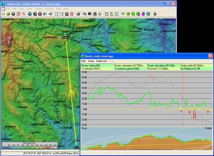
('Left Click' for a higher resolution picture.)
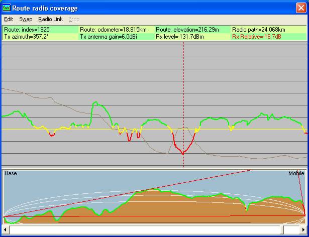
The Route Radio Coverage pane will open with the cursor at the start point of the Route. The cursor can be moved using the Left and Right arrow keys, or a left click on any point on the grey part of the Route Coverage pane will move the cursor to that location. The Route and Radio Link are shown in Green for signals at +3dB and above the receiver threshold, with Red for signals below -3dB. Signals in the +/- 3dB range being shown in Yellow. Route Elevation is shown as a Brown line in the background of the pane if selected, changing to Blue where there is a Line of Sight path between the Units. The Radio Link line also reflects the signal range colours, and the position of the 'mobile' unit is shown by the red cross wires on the main display, with its location being given at the bottom of the screen. The lower part of the pane shows the ground profile and direction of the active radio path.
Click here to see how to change the Route plot colour thresholds on the Style pane.
The 'mobile' unit can be moved along the display in 'Step' increments using the Left and Right arrow keys, and moved to the route 'start point' with a 'Shift+Left click', or route 'end point' with 'Shift+Right click' on the mouse anywhere in the grey window area.
When small step increments are set using 'Edit/Options' from the Radio Coverage options pane - e.g. 10m - a scroll bar will appear at the bottom of the Radio Coverage pane, as only a portion of the route will appear in the window. A click on the scroll button causing it to blink, will allow the point on the route being viewed to be moved using the arrow keys. A 'Tab' will transfer control to the cursor, which then can be moved using the arrow keys. Shift+arrow key places the cursor in centre screen, with the route panning behind it. The 'Shift+click' actions still operate, and the total route radio performance can be examined by moving the scroll button. To return the expanded view to the Cursor position, 'Left click' in the top green area of the window (or use Shift+ an arrow key).
This pane has all the route data in the green area. The 'Route elevation' displays the route elevation at the cursor position, the 'Route odometer' showing the linear distance along the route to where the cursor is placed. 'Radio path' shows the length of the direct Radio path to the 'mobile' unit from the fixed unit, and the bearing of the Unit. The Route data can be saved in a Text file by using 'Edit/Save data'. To find the Total linear Route length, a 'Shift+right click' in the grey area will place the cursor at the Route end point, with the Odometer then giving the total Route length.
As an example of the Line of Sight path display, this is the L1X-Ash-Bux.plt route displayed (available in the root of the RM folder). The total route is some 32km long, traversing my Base map from bottom centre to the North West top corner.
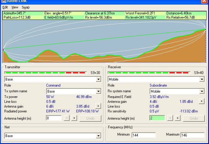
By Clicking on the 'Radio Link' button on the 'Route Radio Coverage' pane, the Radio Link pane opens, showing all the details for the Radio Path. It should also be noted that, when the position of the cursor is moved within the Radio Link pane, the red cross-wire cursor reflects this position on the radio link selected, and displayed, on the main map. It is also possible to select Radio Paths between the Mobile Unit and any other Unit - or any pair of Units - using this pane to check the path performance. All features of the Radio Link pane are available such as viewing one Unit from the other. Closing the pane causes the display to revert to the 'Route Radio Coverage' function once more.
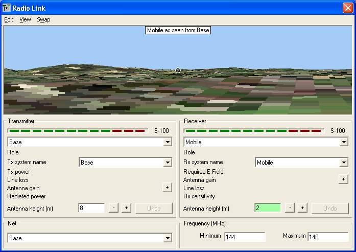
Selecting 'View/Observe 40 degrees' over the aerial view produces this picture, showing that the Mobile Unit is Visible from the Base Unit by a white circle round the Unit position.
One other control button 'Swap' above either screen allows the transmission direction of the link to be reversed and calculated.
Finally, when the Route Radio Coverage pane is closed you will be prompted as to whether you wish to keep the route in the picture, in a new picture or discard.
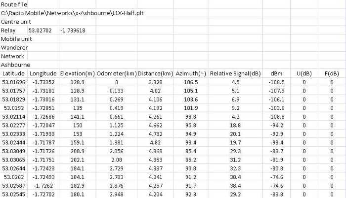
Route data export: Route data can be saved using 'Edit/Save data' where either *.txt or *.kml format can be selected. When Route.txt is saved the format is shown below when entered into Excel to preserve the data columns. The particular route shown is for our local Half Marathon course.
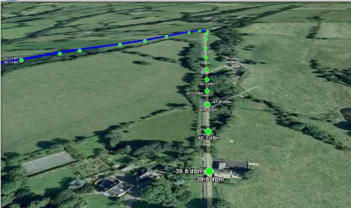
Whilst Route.kml will open Google Earth (if installed on your computer) when saved and clicked, producing a file called 'Route radio coverage' in the Temporary places folder. This file can be expanded to show two folders for the Half Marathon Route 'L1X-Half.plt' and 'Data'. Selecting 'L1X-Half.plt' will produce a Tour button below the temporary places pane, and a click on that will allow the route to be flown with the normal Tour control settings of Google Earth being operational.
Adding the additional selection of the Data file produces a plot as shown below (after adjusting the tour view angle to 65°), where the route is shown and also the waypoints where signal strength was calculated, with the levels shown for the immediate points on the route. The green dots indicate that the signal levels are above the upper limit set on the 'Style' pane, and these change to yellow for the intermediate range and red below the lower limit.
Keyboard and mouse Shortcuts on the Route Pane
Note: When small step increments are set using 'Edit/Options' from the Radio Coverage options pane - e.g. 10m - a scroll bar will appear at the bottom of the Radio Coverage pane, as only a portion of the route will appear in the window. A click on the scroll button causing it to blink, will allow the point on the route being viewed to be moved using the arrow keys. A 'Tab' will transfer control to the cursor, which then can be moved using the arrow keys. Shift+arrow key places the cursor in centre screen, with the route panning behind it. The 'Shift+click' actions still operate, and the total route radio performance can be examined by moving the scroll button. To return the expanded view to the Cursor position, 'Left click' in the top green area of the window (or use Shift+ an arrow key).
Note also that the Land foliage losses can also be incorporated into the plots - to see how, visit:
To find out about 'Split Routes' click here
This page is available in .pdf format here
Please keep checking back for updates/additions.
© Copyright G3TVU 26th October 2017 |