Antenna Pattern Viewer
I can be contacted at E-mail address:-
![]()
Antenna Pattern ViewerI can be contacted at E-mail address:-
|
|
|
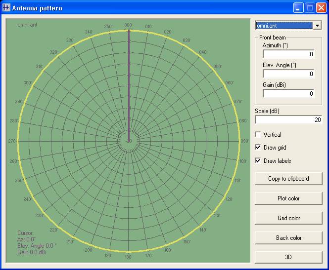
The Antenna Pattern Viewer can be accessed from 'Tools/Antenna Pattern Viewer', or by clicking the Toolbar Icon:
The following Azimuth pattern for the Omni directional antenna will open:
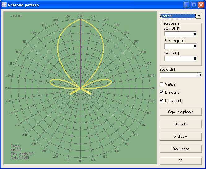
Selecting the Yagi antenna, the following display is shown - this is the Azimuth display of the stored pattern, with the Purple line showing the reference gain direction, with antenna gain as 0dBi.
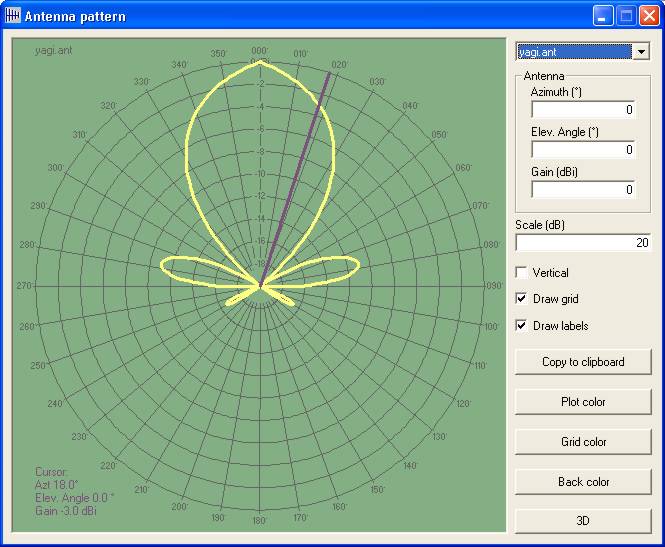
A click in the pattern area, will align the cursor to that point to examine the gain, whilst using 'Shift+right arrow' will increase the cursor angle in 1˚ steps and 'Shift+left arrow' reduces the angle in 1˚ steps, the azimuth & elevation angles and gain being shown in the Cursor data block area.
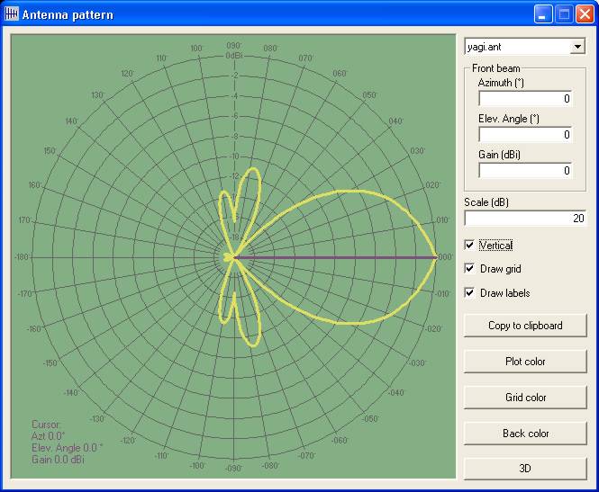
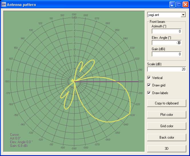
Similarly, selection of the Vertical check box shows the Elevation pattern with reference, whilst using 'Shift+right arrow' will increase the cursor angle in 1˚ steps and 'Shift+left arrow' reduces the angle in 1˚ steps, with azimuth & elevation angles and gain shown in the data area.
Changing the antenna Elevation tilt angle setting to -30˚, then shows:
Where the resulting antenna tilt is displayed - the reference line now showing the actual horizontal gain of -6.8dBi being experienced where it intersects the Yellow beam pattern.
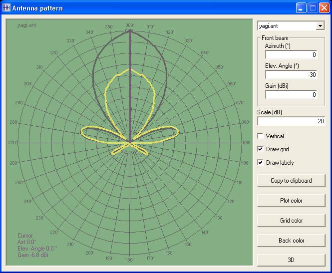
On returning to the Azimuth plot once more, the actual horizontal Azimuth gain is shown in Yellow, with the reference full gain horizontal elevation plot shown as a Black line, actual gain being -6.8dBi as before.
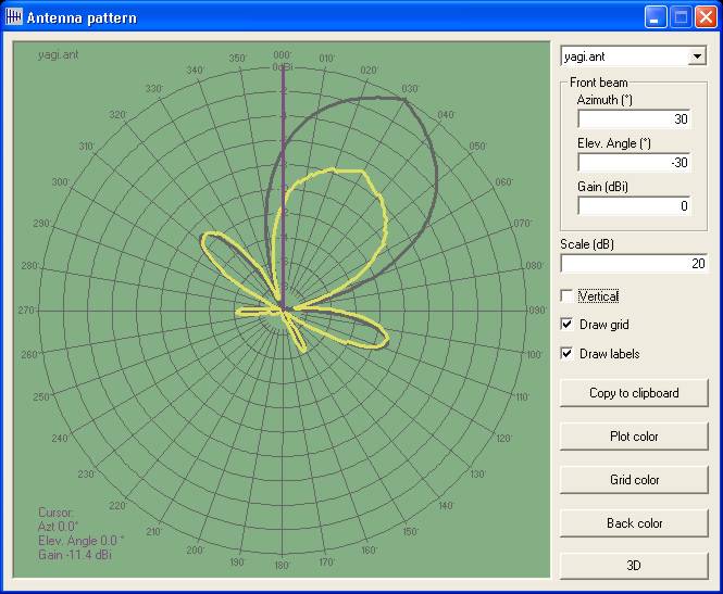
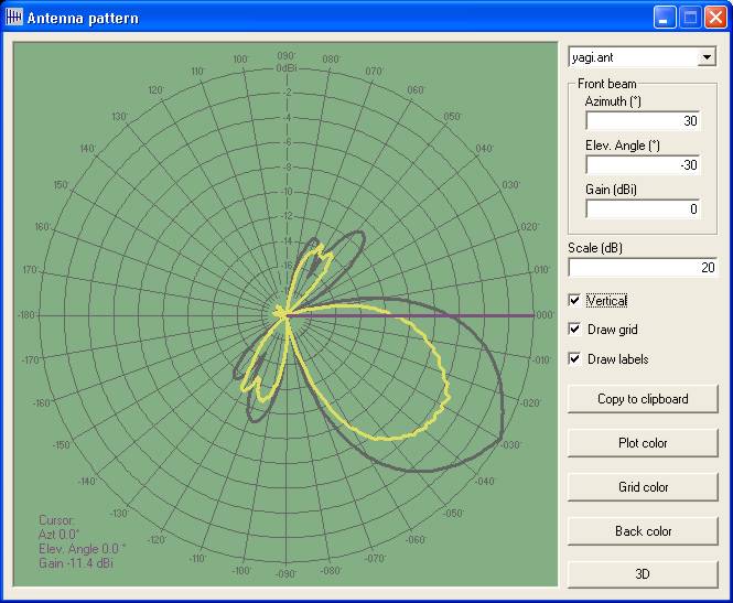
Next, on modifying the Front Beam Azimuth to 30˚, the beam is moved to that heading, and the Purple reference line intersects the Yellow horizontal gain at -11.4dBi
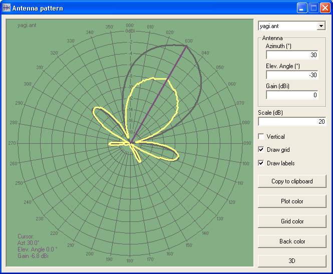
A click on the 30˚ azimuth line then places the cursor at that heading, to show the forward gain available:
Selecting the Vertical plot once more shows the reference azimuth gain in Black, with the Purple reference line intersecting the Yellow pattern at -11.4dBi as above.
In all the cases above, the cursor can be moved to examine the pattern gain using the 'Shift+arrow' function.
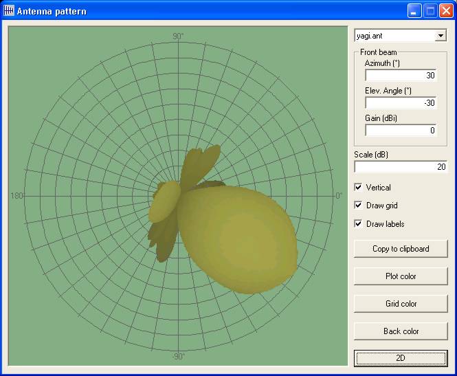
By selecting the '3D' button the vertical pattern is displayed:
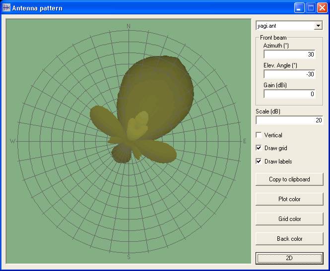
And the corresponding Azimuth 3D pattern:
The pattern viewer can also be accessed directly from the Network Properties, Radio Link, and Route Radio Coverage panes,
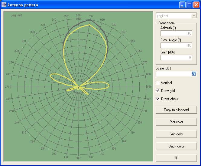
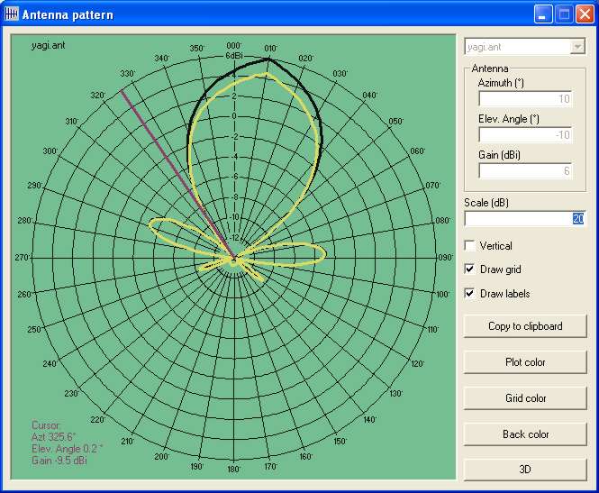
In my Base Network, I have set the Base antenna to be the Yagi above, with a fixed direction of 10˚ Azimuth and -10˚ Elevation, with a gain of 6dBi. By pressing the 'View Pattern' button on the 'Network Properties/Membership' Base setting, the following display is seen, with the settings as per the Network Properties:
showing the selected azimuth pattern for the antenna.
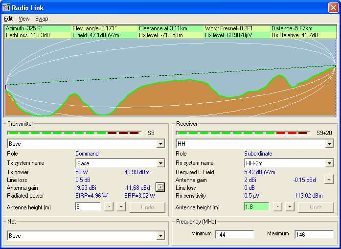
Opening the Radio Link pane with the same settings, to show the Base to HH path:
reports an antenna gain of -9.53 dBi in this link direction for the Base Unit,
Whilst a click on the '+' button under Base Unit Antenna Gain, opens the Viewer to show the reference direction on the antenna Azimuth pattern:
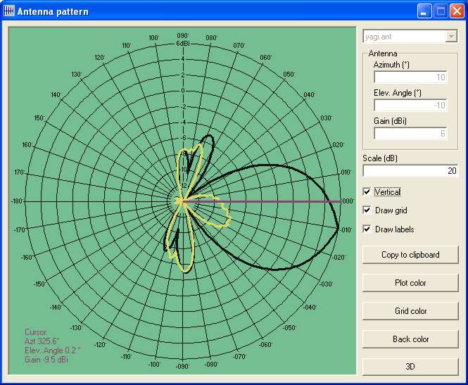
and also on the Elevation pattern
This page is available in .pdf format here.
Please keep checking back for updates/additions.
© Copyright G3TVU 26th October 2017
|