Fox Hunt
I can be contacted at E-mail address:-
![]()
Fox HuntI can be contacted at E-mail address:-
|
|
|
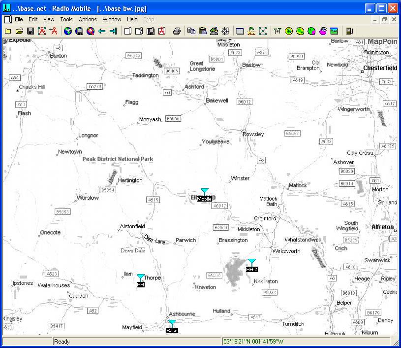
An additional feature available in the program is the 'Fox Hunt'. This is a Radio Amateur Radio Direction finding event. During the event, the 'Hound' searching stations take radio bearings of the hidden 'Fox' transmitter from a number of locations, and where these cross gives a possible Fox location. To demonstrate the use of this feature, I have moved the Mobile Unit in my Base Network to a central road map position as shown below, and the azimuth bearings from the two Hand Held Units HH and HH-2 will be used.
(But also see the additional measurement functions available here)
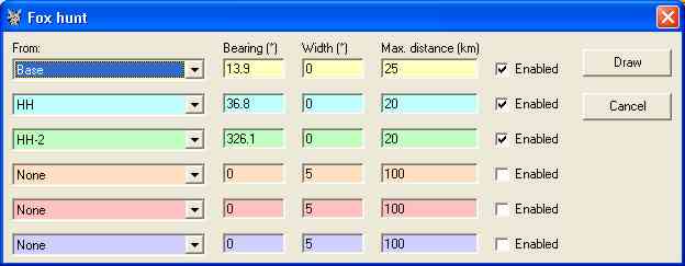
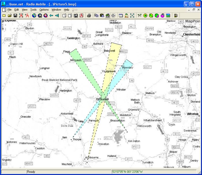
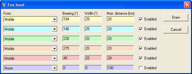
Opening 'Tools/Fox Hunt' generates the pane below, where bearings from up to 6 Units can be entered plus the length of the generated azimuth line defined. The 'Width' here has been set to 0˚ to give a direct bearing line.
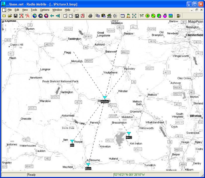
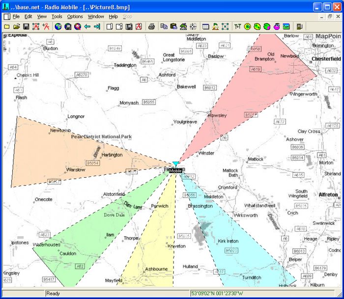
In practice the bearing wouldn't be entered to decimal degrees as above, as the uncertainty in the bearing would limit this to possible 5 degrees at best, but I cheated as I used the link azimuths from the Radio Link pane to obtain these values. A click on 'Draw' will then project the bearing lines on the map as shown. Closing the 'Fox Hunt' pane allows you to select how you wish to keep the picture as normal. This picture3 shows the effect when 'Keep in New Picture' is used.
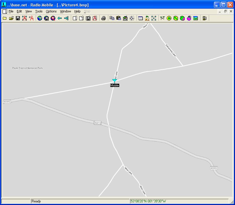
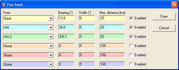
It can be seen that the three bearing azimuths cross at the Mobile Unit, but for a more detailed view, the area round the crossing point can be Zoomed, and merged with a data source. Picture4 shows a merged Road map from Virtual Earth, converted to greyscale, with the Mobile Unit sited at a cross Roads.
Opening 'Tools/Fox Hunt' once more - which retains your previous settings - and pressing Draw, will now draw the azimuth lines on the Zoomed view to confirm that the plot is accurate on my Base Network at a range of 10Km!
In practice this sort of accuracy of location won't be achieved due to bearing measurement uncertainties, but the plot will accurately display the entered values.
If the Fox Hunt pane is opened once more, these bearing uncertainties can be taken into account by entering a 'Width' value for them as shown. It should be noted that the maximum width which can be employed is 150˚.
and when plotted over the road map, this picture will result, showing the area where the mobile unit should be located.
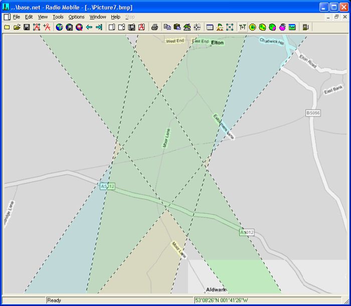
By zooming into the 'crossover' area, merging with a road map once more, then forcing greyscale, the map below is generated - over which the bearing plot has been repeated from the three locations.
Illustrating the power of the technique.
There is no restriction on the allocation of the 'From' Unit, so this can be used for multiple bearing plots from a single unit if required when set as below.
The resultant plot over the road map could now be used to adjust the azimuths of multiple gain antennas to cover selected sets of unit locations.
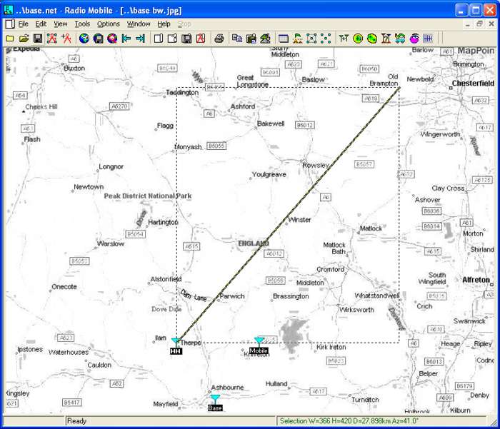
A new facility introduced in the program which should not be forgotten, is an additional measurement feature which is available on any picture showing a Unit. The HH Unit has been selected below, using 'Shift-click' on its icon. This selected Unit is then indicated by having its name font changed to Bold as shown. A Shift-'Left click' on another location on the picture will then produce a volatile yellow/black line between the selected Unit and the location. The Azimuth and distance between the Unit and location are then reported on the Status area of the screen.
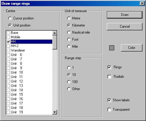
It is also possible to draw 'Range rings' centred on any Unit or cursor location by opening 'Edit/Draw rings' which produces this 'Draw range rings' pane.
This page is available in .pdf format here.
Please keep checking back for Updates/Additions.
© Copyright G3TVU 1st February 2016
|