Antenna Alignment
I can be contacted at E-mail address:-
![]()
Antenna AlignmentI can be contacted at E-mail address:-
|
|
|
When using directional gain antennas, their azimuths may be set to a particular direction, or towards a second Unit if required.
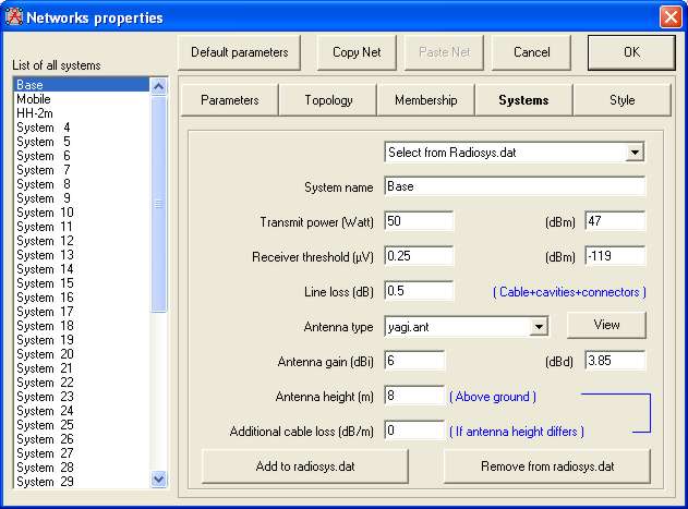
The designated antenna for a particular radio 'System' is selected in the Network Properties pane (File/Network Properties). In the pane below the 'Yagi' antenna has been selected for the 'Base' System in my Base Network. This is where the antenna System gain and height are specified.
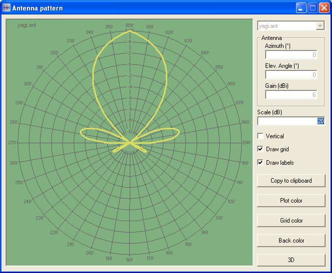
A click on the 'View' button beside the antenna type, opens the Antenna Pattern pane - Please note that this is just a viewer, it isn't possible to change the antenna parameters from here!
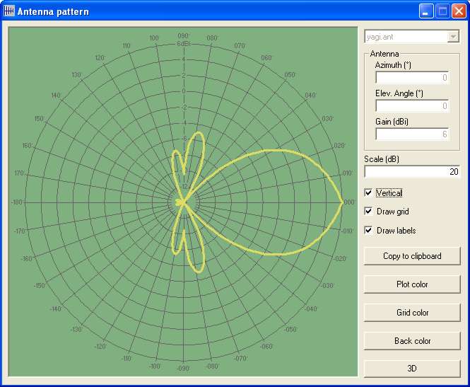
This shows the Azimuth pattern of the selected antenna, and a click in the Vertical checkbox displays its Elevation pattern:
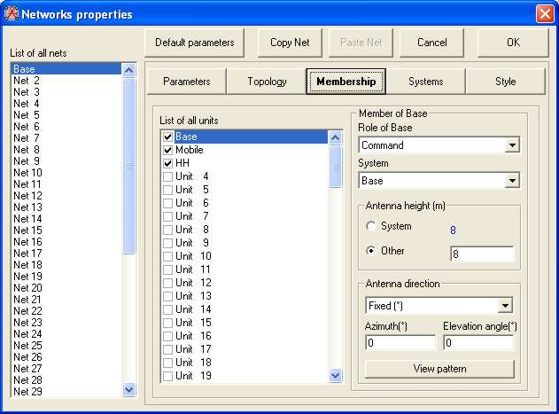
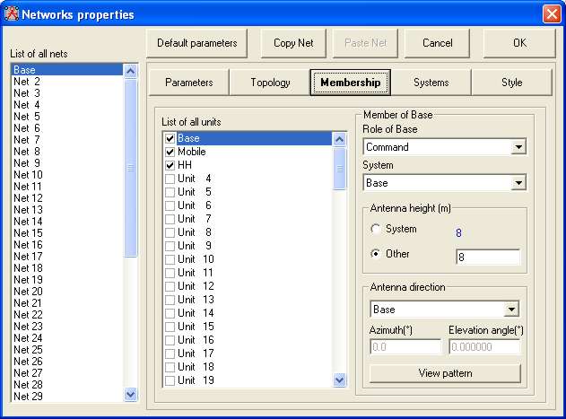
Closing the pattern viewer, and selecting 'Membership' opens this Network Properties pane. At the lower right of the pane is the Antenna Direction area - by default the Azimuth and Elevation are set at 0˚. The Azimuth and Elevation angle tilt required for a fixed antenna can be entered in the appropriate boxes.
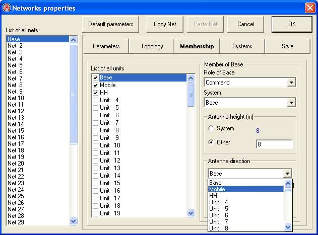
Where the Azimuth is required to be that of another unit, un-checking the 'Fixed' box causes a drop down list to appear showing the Base Unit.
Opening the list allows any other Network Unit to be selected as the antenna azimuth - in my case the 'Mobile' Unit.
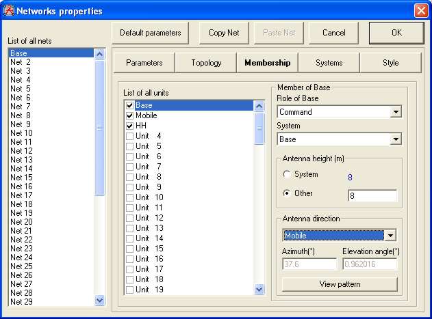
Where the settings shown in Azimuth and Elevation are greyed out, showing the actual signal path parameters:
The Network Properties settings are then saved and the pane closed using the OK button.
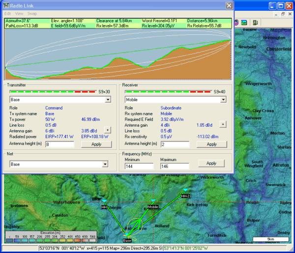
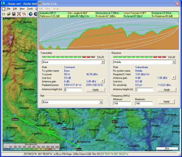
The significance of using the Azimuth of a Unit rather than a fixed degree Azimuth bearing can be demonstrated by opening the 'Radio Link' pane and displaying the Base to Mobile Link.
It can be seen that the antenna pattern is shown at the Base location, superimposed on, and aligned to the radio Link. A left-click on the (+) button by the Base antenna gain, will show the antenna pattern with its correct azimuth on the plot.
If the Radio Link pane is now closed, and the Mobile Unit moved to a new location - click on the location at lower left to produce the cursor, then right-click on the mobile unit to move it! Opening the Radio Link pane once more will give this result.
Where it can be seen that the antenna azimuth has been adjusted to line up with the new Mobile Unit location!
There are a number of different generic antenna patterns available within the program, but if you wish to generate your own, look at Antenna Plots where an Excel worksheet 'Ant Gain Plot.xls' and '3D Antenna 5 degree plot V2.xls' are described and available from my Downloads page.
For more information, look at Antenna Pattern Viewer.
This page is available in .pdf format here
Please keep checking back for updates/additions.
© Copyright G3TVU 26th October 2017
|