Antenna Plots
I can be contacted at E-mail address:-
![]()
Antenna PlotsI can be contacted at E-mail address:-
|
|
|
If the generic antenna radiation pattern forms included with Radio Mobile do not meet your needs, there are a number of spreadsheets available which enable you to enter your own radiation patterns for specific antennas.
Radio Mobile reads an antenna pattern definition text file with an extension of ***.ant which is contained in the 'Antenna' folder of RM. The file format is a list of gain values for an antenna at 1˚ intervals, but shown from a maximum gain of 0dB. Thus the list shows the antenna gain as -ve dB's relative to the maximum antenna gain which produces an Antenna Pattern for RM and the actual antenna gain value is entered in the 'Radio Operating System' allocated to the Unit on the 'Network Properties' (Ctrl+N) pane. There are three versions of antenna pattern files recognised by RM:
The first two spreadsheets, 'AntDiag.xls' and 'Antenna Pattern Creator with FCC relative.xls', only allow Version1 2-Dimentional Azimuth only antenna data to be entered at 10˚ intervals but require the data to be converted to negative dB's before entry to generate the pattern. The program then performs linear interpolation between the 10˚ points and generates the 1˚ list for copying and import into Radio Mobile. These spreadsheets are available via the links, my RM Downloads page, or from the Group Files section.
Following the addition of full 360˚ 3D antenna patterns, I have now produced a new updated version 2 of a 3D spreadsheet named '3D-360 degree antenna plot accepting phased verticals'. This sheet accepts actual antenna gain data and also generates patterns where the maximum Elevation gain can lie below 0° elevation - in this case the actual 0° gain has to be entered as the Azimuth gain for all angles to generate the ***.ant file.
With the new spreadsheet actual Azimuth and Elevation gain data may be entered in 5° or 10° increments as desired. Where 10° entries are used, the 5° data points should be left Blank, and then the 10° points will be interpolated into the 1° steps required by RM ***.ant files. Where 5° data is entered this will be accepted and interpolated to 1° steps.
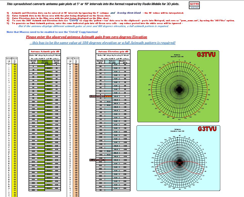
The datasheet Azimuth antenna gain entries should be entered into the Green data area - with the corresponding Green chart showing the pattern entered. But make sure that you enter your actual antenna Azimuth gain at 0° for Omni patterns! Failing to do this will give an overflowed pattern shown on the spreadsheet charts which will not work. Elevation antenna gain entries should be entered into the Blue data area - with the corresponding Blue chart showing the pattern entered. Make sure that you examine the sheet Elevation degree format if you are pasting 5° data from Eznec, otherwise you will obtain an incorrect pattern shape but this will be shown immediately on the spreadsheet charts.
Note that any data entered into the white boxes in the green or blue entry areas will be ignored - this is to allow pasting of gain values for Omni antennas into the whole column.
Macro's need to be enabled to perform the selective Copy function, and 'Ctrl+Q' will copy the V3, 3D data to the clipboard when required. 'Ctrl+Q' now controls the macro copy function as it is an unused shortcut in Excel.
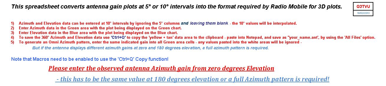
1) The instructions shown below appear at the top of the spreadsheet with its release date:
2) The new version: 3D-360 degree plot accepting phased verticals
The sheet has now been revisited to provide a better chart display and also to allow 0dB values to be inserted if required in the Azimuth and Elevation data columns. (Click here for Eznec data entry information)
The sheets contains a macro to perform the required 'Data copy' function: 'Ctrl+Q' copies the Full Azimuth plus Elevation (Yellow plus Tan) (Version 3) data to the clipboard.
Next the data needs to be pasted into Notepad (or other text editor), and then using 'Save as' select 'File type' to be 'All Files', and enter 'Your_name.ant' as the file name. The file can then be saved in the Radio Mobile Antenna folder for use.
This spreadsheet is protected to avoid entries into critical areas, but your data can be manually copied from the Yellow and Tan areas of the 'C' column if required - all 720 entries - hence the macro!
Instructions for use are included at the top on the spreadsheet, but are repeated here for information:
1) Actual Azimuth and Elevation gain data can be entered at 10° intervals by ignoring the 5° columns and leaving them at Blank - the 10° values will be interpolated.
2) Enter datasheet Azimuth gain data in the Green area with the plot being displayed on the Green chart. But make sure that you enter your actual antenna Azimuth gain at 0°
3) Enter datasheet Elevation gain data in the Blue area with the plot being displayed on the Blue chart.
4) To save Full Azimuth and Elevation data use 'Ctrl+Q to copy the 'yellow + tan' data area to the clipboard - paste into Notepad, and save as ''your_name.ant', using 'All Files' option.
5) To generate an Omni Azimuth pattern, enter the same gain into all Green area cells - but if the Elevation plot has its maximum gain below 0°, make sure you enter the Elevation pattern 0° gain value as the Azimuth gain! - any values pasted into the white areas will be ignored.
6) Check that your elevation data at 0° and 180° are the same value - if not a full 360° Azimuth pattern will have to be entered to allow for this.
If you wish to import data from Eznec into the spreadsheet, perform a 'Far Field' plot for Azimuth and Elevation at 5° intervals. This data can then be imported into a spreadsheet to enable the columns of data to be separated and copied for pasting into my 3D spreadsheet. If you use 'Paste Special/Values' for the data, the spreadsheet colour formatting will be maintained with the 5° data being ignored in the 10° column - and 10° data ignored in the 5° column. Note that Eznec data output comes as a 0° to 360° listing for Azimuth, but only 0° to 359° are required by RM. The Elevation data is in the same 0° to 360° format, but needs to be copied into the correct cells on the spreadsheet as RM uses +90° to 0° to -180° then +179° to +91° as the entry format shown in Version 3 above. The charts will show the interpreted pattern data on the spreadsheet.
Please note that if you wish to share your *.ant files with someone else that they should be zipped before attaching to an email, as additional characters can be added to these 'text format' files if sent as attachments.
Please keep checking back for updates/additions
This page is available in .pdf format here
Please keep checking back for updates/additions.
© Copyright G3TVU 26th October 2017
|